
Gents, I need some additional brains on this problem. I am working it out but some additional "ideas" are always fitting. I apologize for it's length, hopefully you can enjoy the read.
Background:
I had a fully functional set of tail lights, stock, worked great, local sheriff did not like the fact that the colors are twisted so to speak.
I decided to update to LED. Did my flasher update first. No problems, all worked as before. I then moved forward on tail light replacement actions and took digital photos of my stock set up while doing the removal surgery.
(Wanted a record of wire position, etc.) Got my LED Superlights and some diodes and followed the standard upgrade wiring process as posted on the SDP site. Tested all the diodes after soldering them in and then mounted the lights.
Stunning light, but a problem. I had rear parking lights on both sides, brake lights on both sides but no turn signals on the left, only the right.
I started tracing the circuit, checked the grounds, checked the rear wire connector box and then moved into the breakers.
What I found surprised me! Past owner/user had wired in jumper cables with BUSS automotive fuses on defective breakers. I pulled all the fuses and replaced.
Now I have turn signals on both sides front and rear right, no left rear. I also lost my brake lights on the rear left side. I still have all lights rear light up when parking lights are on.
My next step is to check the remaining OEM breakers for a bad unit and add a jumper wire with fuse if necessary.
My question is...am I missing anything obvious that I have not thought of after studying the wiring diagram for hours and hours? Great puzzle I might add and I have never been much good at them but I am learning!
Thanks for any input.
Bruce
Turn signal circuit demons
Moderator: TechMOGogy
Turn signal circuit demons
1975 710M

This sounds like the "ripping my hair out" event I had when changing mine over to new tailights. Mine are not LED but the wiring is the same I think other than for the diodes. Here is what I finally ended up with:
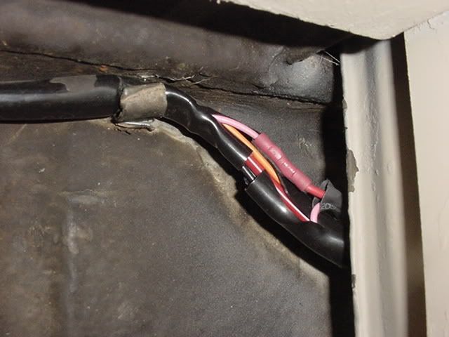
-Brown wire to ground
-Black w/green stripe to RH turn signal
-Black w/white stripe to LH turn signal
-Gray to RH tail light
-Black to LH tail light (along with lic. plate light lead)
-Pink to brake lights.
In the dash I disconnected the Pink wire at S58 on the light switch, lengthened it and connected it to the brake light switch instead of the Orange wire. Found that the Orange wire was either intermittent, didn't work at all or I did not understand the wiring diagram (most likely) but since the Pink wire was not used for anything (old blackout light), this worked great and has continued to work without a problem. Tape off the Orange wire under the dash and just put it out of the way.
Don't know if this will work for you but best of luck!
Paul
Paul C.
_________
'73 Swiss 710M SOLD
'89 Puch 230GE
_________
'73 Swiss 710M SOLD
'89 Puch 230GE
-
Jim LaGuardia

- Posts: 1707
- Joined: Wed Apr 14, 2004 3:42 pm
- Location: San Bernardino Ca
- Contact:
What the hells with the diodes? if you are using 24v LED's and an electronic flasher there is no need to complicate things 
Here is a suggestion, first and formost actuate the hazard switch several times(all turn and brake functions pass through it)
Next verify with a test light at each tail lamp and check all connections at the rear junction box (located by trailer plug), also check the ground wire at the front turn signal of the affected side.
Diodes are directional, if all else fails, remove or bypass them at least while testing functions.
I just went through all of this on Glenn's 712AMB 2 weeks ago.
Took out the crap 2012 put in and had it all working in less than 30 min
One last thing, make sure the ground wire from the signal lever is attached to the body(this will also affect the high beam circuit.
power comes from #12 breaker for turn signals on MOST trucks.
The PINK wire is usually used to add in backup lights.
-
Jim LaGuardia
- Posts: 1707
- Joined: Wed Apr 14, 2004 3:42 pm
- Location: San Bernardino Ca
- Contact:
First a bit of caution for those not familiar with working with electrons, TURN OFF GROUND SWITCH BEFORE YOU BEGIN  Now that said, an easy way to wire in the back-up lamps is to use the pink wire on the rt side of the headlamp switch, move it to an ignition power source on the IGNITION SWITCH, next (I write this as if the pink wire is already removed from the tiny lamp in the factory tail lamp assy and attached to the newly installed BACK-UP LAMP), remove the gas can and find where the harness emerges from behind the fuel tank, carefully open the harsess (cut open), find the pink wire, now cut it and attach each end to a wire from the BACK-UP LAMP SWITCH, next reseal the harness with LIQUID TAPE, after everything is back in place turn on ground switch and "SEE THE LIGHT"
Thanks pcolette and Jim. I will add these points to my exercise!
Jim the diodes are wired in so that the signals are spread out to both tailights and you then duplicate certain action light responses. I could have left them out and just wired each light to the standard wiring scheme. The only difference is the duplication of the circuits with bridging wires containing the diodes. Pretty slick actually, just have to find the break in the circuit!
The emergency flasher works fine, so does the high and low beam headlights. Perhaps it is a bad orange lead on the the left side in which moving to the pink wires is a possible alternative.
1975 710M
-
Jim LaGuardia
- Posts: 1707
- Joined: Wed Apr 14, 2004 3:42 pm
- Location: San Bernardino Ca
- Contact:
Jim wrote: I have never found a cut orange wire , always a corroded plug or bad connection...
Well I have done a quick check on both those items but now I am going back with more testing equipment. Also cleaning up the bridge connectors for those particular wires and the ground connections you mentioned. Remove bolt, clean all surfaces, add some dielectric grease, re-assemble. The puzzle continues...but I thank you for your feed back
Well I have done a quick check on both those items but now I am going back with more testing equipment. Also cleaning up the bridge connectors for those particular wires and the ground connections you mentioned. Remove bolt, clean all surfaces, add some dielectric grease, re-assemble. The puzzle continues...but I thank you for your feed back
1975 710M
-
Jim LaGuardia
- Posts: 1707
- Joined: Wed Apr 14, 2004 3:42 pm
- Location: San Bernardino Ca
- Contact:
Your best bet would be to re-check your connections at the the left tail lamp assembly. As I said before, the brake lights go THROUGH the TURN SIGNAL SWITCH and THE HAZARD SWITCH. The Brake and Turn use the same circuit, the orange wire is an extra circuit in the harness and can be used by connecting it at the 12 wire plastic connector to the right side of the dash, the mating terminal is EMPTY.
I have Three different schematics, so I can understand why it is so confusing at times, I believe the Austrian models used seperate brake /turn circuits, and that may be why the orange wire is not used on the Swiss models
Stock Swiss wiring is as follows:
-Brown wire to ground
-Black w/green stripe to RH Brake/turn signal
-Black w/white stripe to LH Brake/turn signal
-Gray to RH tail light
-Black to LH tail light (along with lic. plate light lead)
Hope this helps.
Jim wrote: "The Brake and Turn use the same circuit, the orange wire is an extra circuit in the harness and can be used by connecting it at the 12 wire plastic connector to the right side of the dash, the mating terminal is EMPTY."
Jim, OK, let me see if I understand this. When using the orange wire it has to be connected to the clear plastic connector under the dash? Which terminal connection does it need to connect to? Isn't it already there? If it is not by default were is the end connected now?
I guess I am rather confused that my right rear brake lights and turn lights work fine but the left do not and I am using the orange wire!
I know I have a short somewhere preventing current from arriving at the left turn and stop lights, I just haven't managed to find it YET...
My problem is finding enough time to stick with it. We are lambing now so things are kind of hectic. I hope to do more trouble shooting on the rear end of things tomorrow. Today was checking as many ground points and connectors under the dash that I could.
1975 710M
-
Jim LaGuardia
- Posts: 1707
- Joined: Wed Apr 14, 2004 3:42 pm
- Location: San Bernardino Ca
- Contact:
If everything was working before the installation, you really need to back-up and re-visit items installed. Diodes only allow current to flow one way.
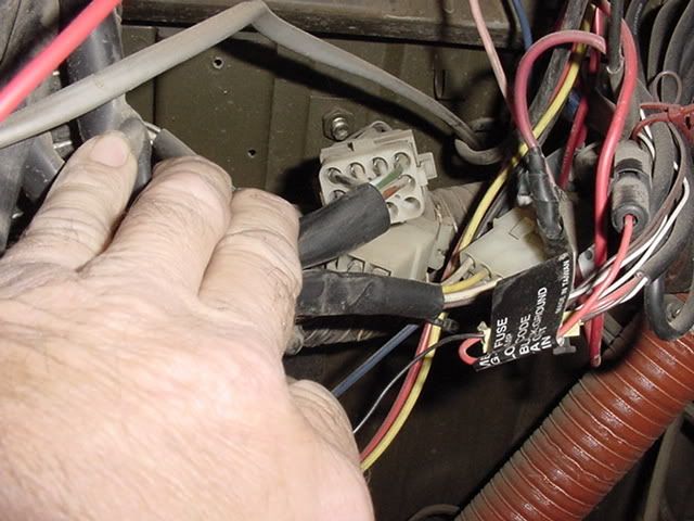
Basically you are tracing an "open" , a "short" will trip the breaker., considering you have one side working, you should use a test light at the tail lamp harness . Here is a picture of the under dash connector, notice the empty terminal on mine. If there is an open in the orange wire downstream, it would have to be in the junction box by the trailer plug.
Here is the schematic:
here is a link to the .pdf
http://www.goatwerks.com/images/swissschematic.pdf
You will notice the orange wire is not connected to any lamps in the stock tail lamp .
Thanks Jim,
I have been testing most of this a.m. About the ground to the turn signal switch, I have checked it.
What is the ground wire that runs up the steering column ?It passes down the lower foot well, under the steering gear housing and into the steering column! Is that for horn? Strange route...
I am getting ready to tear out the diodes and go back to standard wiring on both sides. Nice experiment but I am loosing patience with it.
The wiring diagram you linked is the one I have finally settled on as being the most reliable. The part #62 threw me for a loop though but I think it's just given a funny name! Same as #24 on the manual diagram, Light switch relay ? If not were the heck is #62 Hazard lights control box...not to be confused with the Hazard light switch #60 (Switch for all around flashing light...)?
BG
1975 710M
Demons gone!
Turns out it was the turn signal switch! Replaced with a known good unit and all lights, turn signals and brake lights now work ON BOTH SIDES! Thanks to all for the ideas and support!
Bruce
Bruce
1975 710M
Bruce....before you throw out that old switch, tear it apart and see if its just debrise or a broken weld, clean it up good and test it for function. Its just a mechanical device that current flows thru, not much to them at all. From the sounds of it you should have a short, either worn wire casing or lose spring cross contacting. Good luck.
Miles
Miles