Gents
Here is a shopping list for parts if you intend to do a DIY upgrade install using a 55 or 75 amp alternator.
There is some soldering and drilling activities to accomplish the job right first time. If you are not a competent solderer then try to find someone who can do it for you or buy a kit from us.
All the following is available from those folks at Napa.
6 off feet of 8 gauge multi strand wire, pt # 738802
1 0ff 100 amp circuit breaker pt # 782-3114
1 off ring terminal part number pt # 721128 (size 5/16)
3 off ring terminal part number pt # 721127 (size 1/4)
1 off grommet to accept the #8 wire
A selection of wire ties.
Some shrink wrap
2 off machine screw #10 for circuit breaker
2 off machine nuts
2 off flat washer
2 off lock washer, and/or loctite
Modus Operandi
Remove the alternator cover, disconnect the batteries (very important).
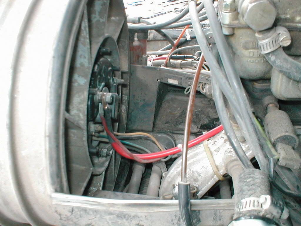
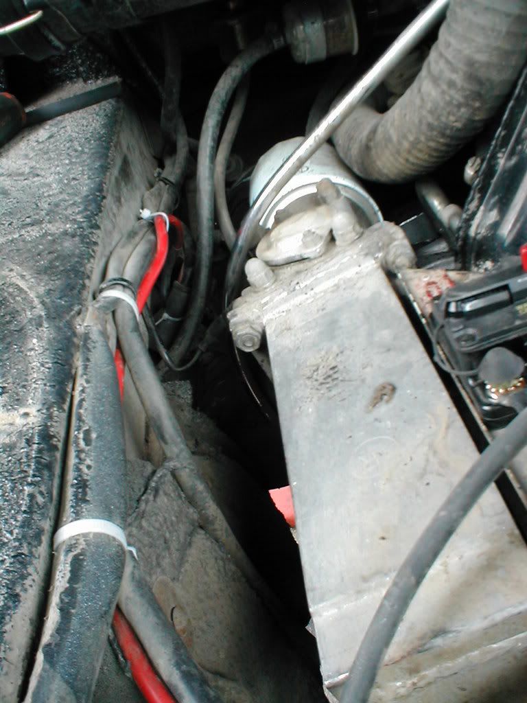
Expose the terminal at B+ve on the starter and loosen the nut with 13mm wrench.
Loosen the nut on B+ve at the alternator with 10mm wrench.
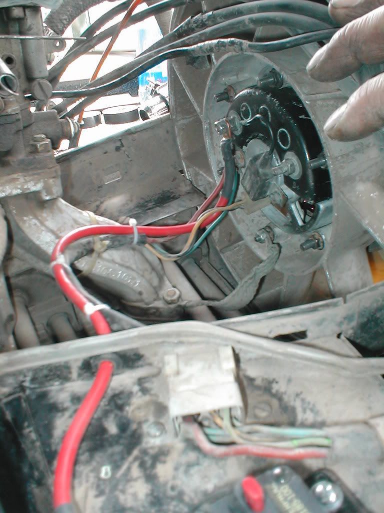
Disconnect field circuit, ground and plug connector. Install upgraded alternator. Reinstall field, plug and most importantly hook up ground wire to mounting bolt.
Remove the molex connector and take a look at the connectors.
Take an opportunity to clean the connectors at this time, repair any that look in poor shape but ignore the left connector (original B+ve if it looks burnt. The ones that need to be kept in good contact/condition are the field wires.
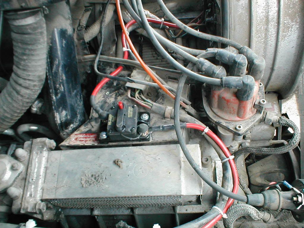
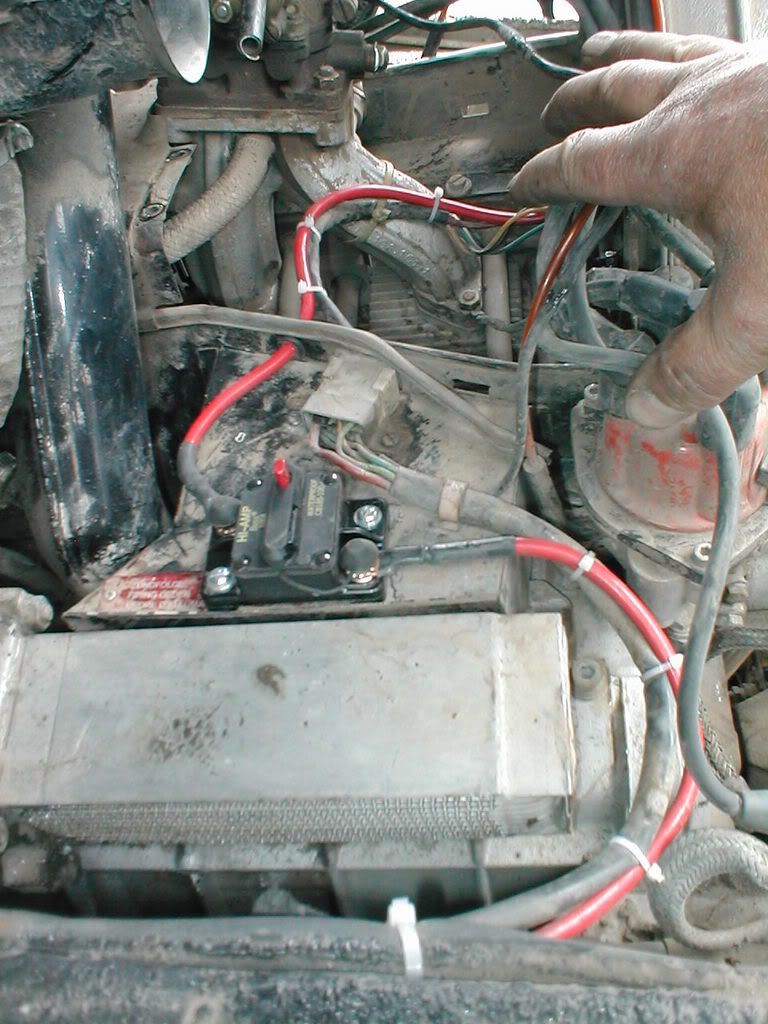
Mount the 100 amp breaker as shown. Use loctite to secure the breaker to the tin cover. (you don't want that flopping about if it comes loose!)
Cut a suitable length of 8 gauge wire to run between the starter post and the breaker. Bare the insulation and solder 5/16" ring terminal to the starter end doing the same at the other end but using a 1/4" terminal.
Don't forget to use some shrink wrap on the soldered ends.
Connect the wire as shown secure both ends and tie up against the existing harness as shown.
Drill a suitable hole in the cooling "tin" as shown and insert the grommet to test. Now make up the link to the alternator using the remaining 1/4" ring terminals soldering them together. Slip this through the grommet and connect as shown. Now use some dielectric grease on the old molex connector and insert it as original.
Take some time to check the field terminals for condition and fraying. If all looks good re-connect the batteries. Check continuity with an volt meter and run up the truck
Test the system with a volt meter stretched across the battery terminals. At idle (900/950r/m) a voltage of about 25.3/26.8 should be seen. raise the revs to about 1000r/m and it should be around 28.2/28.4. Remember there is always a trade off on amp output and threshold performance, so an increase in idle revs may be necessary to get the unit to put the light out.
Once running satisfactorily you can remove/cut out the original B+ve at the alternator and tuck it back with insulation should you wish to downgrade the system at a later date. This is desirable if you intend to use the breaker since should it trip the power will go to the batteries via the original harness that might let the smoke out!
Note you do not need to use the breaker you can put a "jointer" in it s place or even wire directly. You will have to make provision to remove the cover in the future to service the alternator. In the end it's your choice.
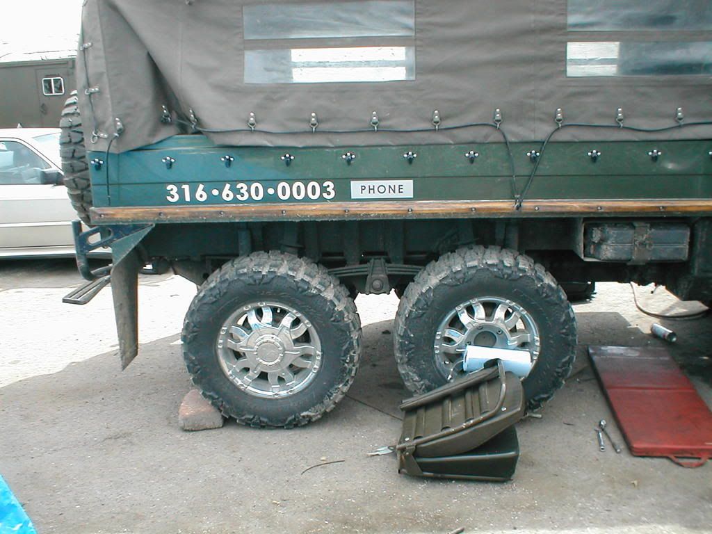
Best of luck and credits to Eric Maybee who had his Pinz done first at our shop and then set of to Wichita through the night with his dog to keep him company. Apparently he arrived safe, but tired. Thanks Eric for your business! Very nice truck
Dennis & John
http://i2.photobucket.com/albums/y14/li ... 010009.jpg
http://i2.photobucket.com/albums/y14/li ... 010010.jpg
http://i2.photobucket.com/albums/y14/li ... 010011.jpg
http://i2.photobucket.com/albums/y14/li ... 010012.jpg
http://i2.photobucket.com/albums/y14/li ... 010013.jpg
http://i2.photobucket.com/albums/y14/li ... 010014.jpg
